|
Thread Number: 37654
/ Tag: 50s/60s/70s Vacuum Cleaners
Need Assistance in Diagnosing D80 |
[Down to Last] |  |
| Post# 401436 11/26/2018 at 09:57 (1,977 days old) by vaclab (Pickerington, Ohio) | ||
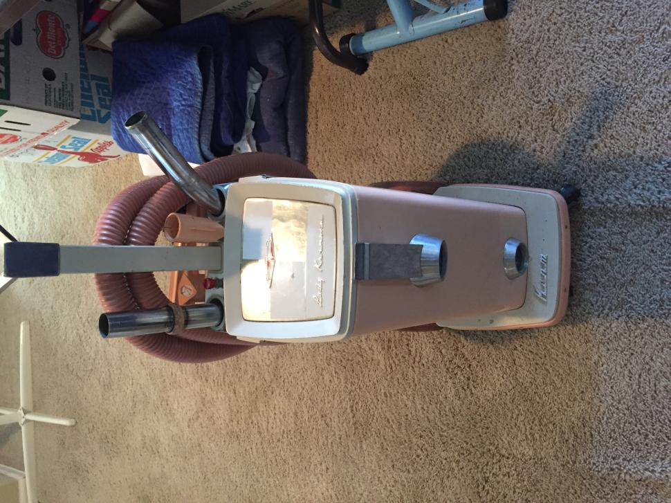
My wonderfully polished D80 will not run after re-assembly. The headlight comes on and I've checked for power at the brushes (brushes removed of course) and I see 121 volts, sooo I need help making my shiny beauty run once again. I know these machines had issues with switches and wiring, but so far, I can find no obvious problem. I have no issue re-wiring it to run on low speed permanently but would prefer not to do that.
With an ohm meter, would anyone know what the various readings should be at various testing points? Bill | ||
Post# 401440 , Reply# 1 11/26/2018 at 12:00 (1,976 days old) by KirbyClassicIII  (Milwaukie, Oregon) (Milwaukie, Oregon) |
||
vaclab | ||
| Post# 401441 , Reply# 2 11/26/2018 at 12:09 (1,976 days old) by bnsd60m9200 (Akron OH) | ||
i have a service manual from that era | ||
| Post# 401451 , Reply# 3 11/26/2018 at 16:07 (1,976 days old) by Louvac (A) | ||
|
Sounds like Sounds like the speed control switch is bad. It makes contact for the light but no contact for the motor. I am willing to bet this is the problem. Direct connect the motor to see if it runs. | ||
| Post# 401460 , Reply# 4 11/26/2018 at 18:29 (1,976 days old) by Lesinutah (Utah) | ||
Hey | ||
| Post# 401471 , Reply# 5 11/26/2018 at 19:54 (1,976 days old) by vacman1961 (North Babylon, New York) | ||
|
Are you sure the carbon brushes are hitting the commutator on the armature? | ||
| Post# 401475 , Reply# 7 11/26/2018 at 20:24 (1,976 days old) by texaskirbyguy (Plano, TX) | ||
|
Also exercise the speed/safety switch to check for possible burnt/bad connections inside of it (but watch your fingers when doing so!) | ||
| Post# 401481 , Reply# 8 11/26/2018 at 21:28 (1,976 days old) by vaclab (Pickerington, Ohio) | ||
|
Two Speed Switch Wiring
Here's my best guess with the two speed switch. The yellow was loose, so I tinned it and shoved it back in. It's a tight fit now.
View Full Size
| ||
| Post# 401482 , Reply# 9 11/26/2018 at 21:31 (1,976 days old) by vaclab (Pickerington, Ohio) | ||
|
Foot Switch Wiring
The #1 blue-ish wire was so loose that it practically fell off, so I tinned it and shoved it back in. It's a tight connection now.
View Full Size
| ||
| Post# 401483 , Reply# 10 11/26/2018 at 21:33 (1,976 days old) by vaclab (Pickerington, Ohio) | ||
|
Got My Bearing Puller
And now I can re-build the rear bearing (it has a rubber seal).
View Full Size
| ||
|
Post# 401485 , Reply# 11 11/26/2018 at 21:36 (1,976 days old) by Rivstg1 (colorado springs) |
||
bill, I just | ||
| Post# 401486 , Reply# 12 11/26/2018 at 21:46 (1,976 days old) by vaclab (Pickerington, Ohio) | ||
|
Replies to suggestions
To LesinUtah:
1. Bad safety switch <- probably 2. Bad power switch <- maybe 3. The motor is not grounding out or power is grounding out. <- possible Thanks for your kind words, Les! =================================== To TexasKirbyGuy: If it ran before you worked on it, then it should be an easy fix. <- Yes it ran fine before I disassembled it for polishing. First check the wires at the safety switch to make sure none popped out like they do sometimes. <- some popped out and now they are back in If you took any wires out of anywhere, make sure they are back in the right places. <- yup, done Make sure motor brushes are not hanging up in the holder and springs are springy. <- smooth operation and springy Make sure wires are securely fastened to the tabs to the motor brushes. <- measured this with an ohm meter, seems OK. Clean commutator bars if you think polish could have gotten onto them. <- polished and picked out build up between bars with a toothpick. If the above are fine, check the armature for any accidental damage that you might have not been aware of. <- can't seem to find any damage so far. ======================================================== I can't wait to find out what's causing the motor not to spin at all. No sparks, just nothing. But, I do get the light bulb's glorious illumination. I'll keep working on it... Wonder which wires to directly connect for the motor to run at low speed? Bill | ||
| Post# 401488 , Reply# 13 11/26/2018 at 21:57 (1,976 days old) by hmc1981 (St. Augustine, Florida) | ||
My own experience...
Well...
I had a similar issue with it running perfect until i took it apart for polishing. For me, I wound up discovering that I reinstalled the front bearing in reverse (very stupid, yes I know, but it happened). Also, bad safety switch is a very real culprit. It�s super easy to harm the switch during disassembly no matter how careful you are. I�ve a spare unused one laying around. Let me know if you are interested. | ||
| Post# 401491 , Reply# 14 11/26/2018 at 22:02 (1,976 days old) by Lesinutah (Utah) | ||
|
Hey | ||
| Post# 401493 , Reply# 15 11/26/2018 at 22:10 (1,976 days old) by MadMan (Chicago, IL, USA) | ||

Somebody around here should have the wiring diagram for the motor. I could swear someone just posted a similar diagram not a month ago. I'm not familiar with these machines, but I believe the motor is not wired totally straight forward. Like, there's an extra coil in the field for the light bulb, or some weird crap like that. If you say you have power at the brush holders, there should be SOME kind of action from the motor when it's assembled. If nothing else, try assembling it again, power it up, bypass any safeties, and spin the motor by hand, seeing if there's any response.
Actually another good question is, does the armature spin freely when totally installed? Lastly, with everything installed, safeties bypassed, play with the speed switch (and any other switches O_o), and wiggle the wires at any at all points, see if there's any response. This is called the 'wiggle test.' You'd be surprised how often the wiggle test yields some kind of clue. | ||
|
Post# 401495 , Reply# 16 11/26/2018 at 22:16 (1,976 days old) by KirbyClassicIII (Milwaukie, Oregon) |
||
|
MadMan
The only electrical diagrams I have for Kirby vacuums include one for models 505-515 and 516-Sanitronic VII (all single speed) and one for the Heritage II. So it would be cool if Will (bnsd60m9200) could try to upload what he has for models Dual Sanitronic 50/80, as I have a D80 myself (and also a Classic 1CR - the third and last Kirby to use the speed switch in question).
~Ben | ||
| Post# 401498 , Reply# 18 11/26/2018 at 22:38 (1,976 days old) by texaskirbyguy (Plano, TX) | ||
|
Well, ax my previous response as the switches are different between D80 and Tradition. Can a mod delete my last post (and this one)? | ||
| Post# 401499 , Reply# 19 11/26/2018 at 22:41 (1,976 days old) by Lesinutah (Utah) | ||
|
Hey | ||
| Post# 401541 , Reply# 20 11/27/2018 at 18:34 (1,975 days old) by vaclab (Pickerington, Ohio) | ||
|
So the question remains... | ||
| Post# 401548 , Reply# 21 11/27/2018 at 20:49 (1,975 days old) by Lesinutah (Utah) | ||
|
Hey
Here is pic of nos safety switch for a d80.
The right front side of switch is high speed. Green is ground so doesn't mean anything. So guessing yellow red is high white is neutral would be hooked up and black wire from coil and black and white from headlight need hooked up. So 2 white direct hook up to foot switch two black direct hook up to foot switch and ground green wires. Unhook other wires and cap off. This should bypass safety switch run single speed. I believe red is high speed power wire and yellow is neutral wire. Les | ||
| Post# 401554 , Reply# 22 11/27/2018 at 23:36 (1,975 days old) by MadMan (Chicago, IL, USA) | ||
|
I could make a diagram if I had a machine to reverse engineer.
If you want to be sure of your wiring, get an ohmmeter (or multimeter), and ohm the field coil. I don't know, but I'm assuming the motor assembly has... 5 wires. Did I guess right? 1 common, 2 speeds, 2 wires for the light bulb. Well, here's what you do. Take the armature out of the field. Connect one ohmmeter test lead to one of the brush holders (or wherever the brush gets its power [some brushes have a spring that touch a contact, or a braided wire that's attached to the brush]) then connect the other test lead to each of the wires coming from the field coil. tbh, I'm not entirely sure how much resistance you're looking for, but I'd bet any reading at all would infer a connection. Just be sure to test ALL the wires, to be sure you've got the right wire. Write down your findings and repeat with the other brush holder. I'm thinking - but I'm not 100% sure - that you will find two wires that have no connectivity to either brush holder. That'll be that stupid light bulb winding, ignore those wires. Now, you want 1 wire from each half of the field coil winding. It may be tricky to visually pick those. From the wires you ohmed, you'll want 1 wire that has connection to only the 1st brush holder and not the 2nd, and a another wire that has only connection to the 2nd brush holder and not the 1st. With the motor assembled, connect those two wires to 120vac and the motor *should* run at some speed. Alternatively, if you want to skip the above, and/or if you're (rightfully) worried about damaging the motor by hooking up the wires wrong, you could hook it up in series with a light bulb. An actual old fashioned incandescent light bulb. Ideally a 100 watt. It's a little difficult because technically you'd want a bulb of the same wattage as the load you're putting through it, but I don't think you're gonna find a 2000 watt bulb. Anyhow, if the bulb lights up near full strength, you're probably attached to that stupid extra winding in the field coil. I'd say it might not light at all, or very little, if you're attached to the motor properly (or rather on of the two speeds). I hope I'm thinking this through properly. But at least with the light bulb, if nothing else, it will act as a fuse and protect the motor. Though I think it's unlikely to blow the bulb, the bulb lighting fully will indicate a short. Or near short. I suppose it might light the bulb with any connection (because it's not high enough wattage [electricity is hard to think about, so I'm not sure]), which then you wouldn't have learned anything, but you wouldn't have fried the motor, either. Safest bet, anyhow. I hope I'm helping. | ||
| Post# 401613 , Reply# 23 11/28/2018 at 21:06 (1,974 days old) by vaclab (Pickerington, Ohio) | ||
|
Some Continuity Testing Later...
And here's what I found so far. I've checked this with two D80 switches (of course both could be bad I suppose).
High Speed = Green and Yellow wires shorted PLUS White and Red wires shorted Low Speed = Red and Yellow wires shorted ALL switch connections/configurations measured 0.0 Ohms. Coil Winding #1 = Yellow and White wires. Meter read about 1.5 Ohms Coil Winding #2 = Green and Red wires. Meter read about 1.5 Ohms Brushes are clean and springy in their holders with good connectivity to the commutator. I'll do more tests as I find time. Thanks for all the suggestions so far. Bill
View Full Size
| ||
| Post# 401617 , Reply# 24 11/28/2018 at 22:22 (1,974 days old) by MadMan (Chicago, IL, USA) | ||
|
So assuming you're right and your switches are not broken...
View Full Size
| ||
| Post# 401638 , Reply# 25 11/29/2018 at 12:52 (1,973 days old) by royalfan (Chicago) | ||
Cankles 🤦♂️ | ||
| Post# 401668 , Reply# 26 11/29/2018 at 18:20 (1,973 days old) by Lesinutah (Utah) | ||
|
Hey
Maybe because we like the vaclabs fellow and trying to help him out.
Unhook the speed switch. Cap high speed wires. You will have 4 wires hooked up to foot switch. Black and White from headlight. I'm red and yellow for low speed. The power wires I think have a b below the 4 connectors. Hook up black and red to 2 terminals on that side. Yellow and white(headlight on 2 of the 4 w terminals. Carbon brush cap wires are green and black. The green has a ground terminal on switch. The black has a spot too. The 4 terminals are in the side and there is a slot/ terminal on same side as other power wires. This is where the carbon brush wire goes. You can do tests until blue in the face switches don't go out often. Push foot switch on and it should start up. If it doesn't it could be switch highly doubt it though. Your field coil is gone. Hopefully this solves it. Les | ||
| Post# 401677 , Reply# 28 11/29/2018 at 19:58 (1,973 days old) by MadMan (Chicago, IL, USA) | ||
|
I was going to make a motor diagram just based on guessing, but then I looked at the Heritage II wiring diagram, and it's insane. They could have just used a normal two speed motor, and a normal 120v light bulb, but NO~OOO. So instead of guessing on something that complex, I just prettied up the switch diagram.
Link below has Ben's Heritage II wiring diagram, which I honestly doubt is all that different, so it'll probably be helpful, but obviously take it with a grain of salt. Let me just mention that I find it ridiculous that the Kirby people making the service manual were thoughtful enough to show you EXACTLY how the windings in the motor are wired in relation to everything else - very helpful, but had no such inclination to show you how the switches work. CLICK HERE TO GO TO MadMan's LINK
View Full Size
| ||
| Post# 401684 , Reply# 29 11/29/2018 at 21:57 (1,973 days old) by vaclab (Pickerington, Ohio) | ||
|
As Time Permits
I'll perform more testing. BUT, I have a hard time believing that coil functionality goes "poof!" simply by carefully removing an armature. There could be micro-cracks in the various lead wires and/or where they connect into the switches though. Since both coils appear to measure the same 1.5 Ohms, I'm leaning towards the coils are OK at this time, but who knows?
Remember, I went from a fully functional two speed operation to absolutely nothing...except the light bulb. I need to finish rebuilding the rear bearing (just got the puller a few days ago) before I can fiddle any further. Bill | ||
| Post# 401685 , Reply# 30 11/29/2018 at 22:01 (1,973 days old) by texaskirbyguy (Plano, TX) | ||
|
Make sure the wires for the brushes are secure in the power switch, too. My picture above shows where they go. I had to add a layer of solder on mine to make them more secure. | ||
| Post# 401814 , Reply# 31 12/2/2018 at 20:53 (1,970 days old) by vacuumdevil (Vacuum Hell ) | ||
|
| ||
| Post# 401832 , Reply# 32 12/3/2018 at 10:39 (1,969 days old) by royalfan (Chicago) | ||
|
| ||
|
Post# 401856 , Reply# 33 12/3/2018 at 14:38 (1,969 days old) by rivstg1 (colorado springs) |
||
|
royalfan | ||
| Post# 401870 , Reply# 34 12/3/2018 at 19:55 (1,969 days old) by vacman1961 (North Babylon, New York) | ||
|
Vaclab, if you want to send me the motor unit for your Kirby I will repair it for you no charge, I am in New York and have been a Kirby Area Distributor for 30 years. Message me if you want my name and address. | ||
| Post# 401871 , Reply# 35 12/3/2018 at 19:57 (1,969 days old) by Lesinutah (Utah) | ||
|
Hey
Every one is entitled to their opinion. I know alot about Kirby's,royals,riccars, Hoovers. He tested a multitude of vacuums. I think your viewing impairment isn't obvious. I guess we are all impaired somehow. He has helped and answered questions about airflow tests. He has helped a professional vacuum reviewer with vacuum info. He is not mechanically inclined. But it's okay he asked for help we helped him. This is spread your knowledge and help each other. That is all.
Les | ||
| Post# 401913 , Reply# 36 12/4/2018 at 12:44 (1,968 days old) by Ultralux88 (Denver, Colorado) | ||
I think you�re wiring the power switch wrong. I see green wire in the black wire spot and vice versa... Here is a picture based on the labeling of the switch.
View Full Size
| ||
| Post# 401949 , Reply# 37 12/4/2018 at 18:58 (1,968 days old) by Lesinutah (Utah) | ||
|
Hey
The headlight follows the colors. Power wires are yo go in black slot even if it's not black. B is + connection white is neutral- ground is making sure wires and electricity follows flow. The neutral wires I use a wire nuts and a pig tail. Wire one wire. Ground the same and power too. It turns headlight and motor on once you push the switch bypassing safety switch.
That way you can see 3 wires basically makes process of elimination easier. Les | ||
| Post# 402096 , Reply# 38 12/6/2018 at 21:19 (1,966 days old) by vaclab (Pickerington, Ohio) | ||
|
For everyone that has made a positive contribution
I thank you and will follow up when I next get the chance. Remember, I do have a full time programming job and a family so my time to complete this machine isn't infinite.
And for the naysayers and haters (you know who you are), let me give you a little biography of some of the things I've done in my nearly 54 years on this earth. - Had a soldering iron and screwdriver in my hand at 5 years old (did a lousy job). - Built my first electric motor around 1977, hand winding the coils, etc. - Compiled my first computer video game on a Unix mainframe in the fall of 1979. - Passed several FCC exams starting in 1979 that essentially mean I can build/repair transmitters and antennas. - Started doing my own automotive maintenance in 1984. Mostly stopped by 2014. Replaced suspensions, did AC, some electrical, wheels, tires, brakes, tune-ups, valve lash adjustments, etc. Have re-programmed my BMW's firmware (in German) to add/subtract/adjust various features. Bimmerfest.com is a great resource for more info. - Dry-walled my garage in 2006, repaired my gas hot water heater and glass top electric stove, not to mention keeping my 1990 Maytags running for 27 years. - As side job in college, I repaired oscilloscopes and that in turn morphed into TV/VCR repair of new and vintage audio visual equipment from about 1983-1997. - Just for fun, over 25 years ago, I started designing and building my own audio amps, mics, testing equipment and high end power supplies. Some of this can be seen in my videos. I could go on about surface mount component repair (I need a magnifying glass for this), but you've probably stopped reading this drivel by now... So gee whiz, I guess I'm just not mechanically inclined enough to handle a 50 year old vacuum cleaner. :) Bill | ||
| Post# 402100 , Reply# 39 12/6/2018 at 23:27 (1,966 days old) by MadMan (Chicago, IL, USA) | ||
|
| ||
| Post# 402101 , Reply# 40 12/7/2018 at 00:04 (1,966 days old) by vacuumdevil (Vacuum Hell ) | ||
|
@MadMan
Don't take this the wrong way. Simplicity synergy Riccar radiance has a 32 pin wire harness. Also the Hoover dimension 1000 form the 1980s , had a lot of wires going inside. They've gotten more and more complicated as the years have gone by. From my perspective I wish they were all like this. @vaclab Can't wait to see the finished machine. | ||
| Post# 402103 , Reply# 41 12/7/2018 at 07:43 (1,966 days old) by vaclab (Pickerington, Ohio) | ||
|
The story so far...
I think there might be some misconception about the wiring. Specifically, the D80 was working 100% before disassembly for polishing. BUT, I never removed any wires, wiring harness, coils or power switch. I did (carefully) remove the speed switch from the front fan case but left all wiring intact.
You can see me polish the headlight hood while everything is still attached to the motor casing in the first post. I also removed the armature in order to replace the front bearing (done) and re-pack the rear bearing (TBD). Charlie (NY) thanks for the offer and I will take you up on it if/when all else fails. Reggie, here is a different pic of the power switch wiring. Again, nothing has been touched, except re-tinning the brush holder wire (#1 in above pic). Bill
View Full Size
| ||
| Post# 402106 , Reply# 42 12/7/2018 at 09:22 (1,966 days old) by bnsd60m9200 (Akron OH) | ||
|
silly question | ||
| Post# 402148 , Reply# 43 12/7/2018 at 20:23 (1,965 days old) by Lesinutah (Utah) | ||
|
Hey
The carbon brush ground wire is in the b which is power.
The carbon brush wires one is black one is green. If the green you have is a ground it needs to go next to the white in g slot. The black carbon brush would go in the b slot. It could be those wires got switched. I don't know you may be able to do it. Don't worry everyone sucks at soldering. I think they make soldering iron $itty so everyone is no good at it. Les | ||
| Post# 402151 , Reply# 44 12/7/2018 at 21:57 (1,965 days old) by MadMan (Chicago, IL, USA) | ||
|
Les, what do you mean? Soldering is easy, even with a crappy iron.
...are you using flux when you solder? Cuz I have a friend, who for the longest time thought that flux was for idiots, while it took him a month to solder a 20 pin plug. Finally I coerced him to buy some flux, he finished his project in a day, came back with a smile on his face and thanked me heartily. I've found that a lot of people are like that. Some weird stigma about using flux. | ||
| Post# 402177 , Reply# 45 12/8/2018 at 10:33 (1,965 days old) by Lesinutah (Utah) | ||
|
Hey
I use flux. I know what my problem is. I didn't have a heat gun so I melted heat shrink with soldering gun. I need to clean head and usie heat shrink gun I have.
I can solder I have to have the roach clip in a football goalposts holder to keep wires in place. I always dip in flux before soldering. I didn't realize until now we'll I realized but it just clicked that's why it's not soldering well. Les | ||
| Post# 402842 , Reply# 46 12/19/2018 at 09:35 (1,954 days old) by vaclab (Pickerington, Ohio) | ||
|
EUREKA!
or maybe I should say KIRBY!
The D80 lives AGAIN! While you will see a video fairly soon, the issue ended up being the green carbon brush wire. At the point where it connects to the brush holder, there was an intermittent connection. AND the connection point to the power switch was also sketchy. I've rebuilt that weird rear bearing and am finishing the final assembly soon. Thanks for everyone's ideas, Bill | ||
|
Post# 402843 , Reply# 47 12/19/2018 at 09:46 (1,954 days old) by KirbyClassicIII (Milwaukie, Oregon) |
||
|
vaclab | ||
| Post# 402845 , Reply# 48 12/19/2018 at 12:27 (1,953 days old) by kirbyklekter (Concord,Ca.) | ||
|
Made my morning Bill, So glad you found the problem. I know I learned a thing or two just following your journey, Bill | ||
| Post# 402861 , Reply# 49 12/19/2018 at 22:19 (1,953 days old) by Lesinutah (Utah) | ||
|
Hey | ||
| Post# 402992 , Reply# 50 12/23/2018 at 16:31 (1,949 days old) by vaclab (Pickerington, Ohio) | ||
|
Les, The Magic Kirby Pixies From Cleveland | ||
| Post# 403000 , Reply# 51 12/23/2018 at 22:01 (1,949 days old) by Lesinutah (Utah) | ||
|
Vaclab | ||
|
Post# 428206 , Reply# 52 7/5/2020 at 23:32 (1,389 days old) by KirbyClassicIII (Milwaukie, Oregon) |
||
|
My D80's Wiring to Foot Switch
I did not yank any of the wiring from the foot switch, just so you know. The foot switch is the same "pressure lock" type (110566) as yours, because I know my D80 was built in 1969.
When you study the first picture, all of the wiring went into all of the appropriate colored slots: all three green wires in the three G slots, all three whites in the three W slots, and both blacks in their two B slots. The third picture shows the green brush lead wire is on the top motor brush assembly, not the bottom one like on my Classic 1CR. The black brush wire serves the bottom motor brush assembly, and its bare wire end goes into the first B slot of the foot switch. ~Ben This post was last edited 07/06/2020 at 00:09 | ||
|
Post# 429568 , Reply# 53 8/5/2020 at 23:12 (1,358 days old) by KirbyClassicIII (Milwaukie, Oregon) |
||
|
VacLab
Bill,
Here's some pictures of the foot switch wiring on my parts D80 that I got yesterday from Thom (KirbyCollector)... they are exactly in the same positions as on my working D80, again, nothing altered. Both my D80s have these wires going into these slots: Green #1: green wire of field coil Green #2: green wire of brush lead (top carbon brush) Green #3: green wire of speed switch White #1: white wire of headlight socket White #2: white wire of speed switch White #3: white wire of field coil Black #1: black wire of headlight socket Black #2: black wire of brush lead (bottom carbon brush) ~Ben | ||
| Post# 429717 , Reply# 54 8/9/2020 at 11:40 (1,354 days old) by Ultralux88 (Denver, Colorado) | ||
|
| ||
| Post# 430087 , Reply# 55 8/15/2020 at 13:55 (1,348 days old) by Lesinutah (Utah) | ||
|
Wiring
The switch has g for ground w for white/neutral and b for power wires.
If you use a voltage meter the whites when touched with whites would show current. The grounds would show current. The power wires wouldn't. This means they don't go together. If you put a wire but on all the whit and ran a pigtail to the switch it would work. If you did the same to the ground wires could be combined. The power wires have to be separated. Les | ||
| Forum Index: | 
| Other Forums: |

|

|

|

|

|
 Comes to the Rescue!


;)
;)
;)
;)
;)
;)
;)
;)